Design and Simulation of a Single-Phase Induction Motor for Ceiling Fans
Ceiling fans are one of the most common applications of single-phase electric motors. Although the motor used in a ceiling fan may appear relatively simple, designing it for high efficiency, low cost, low noise and adequate starting performance involves several competing requirements.
This becomes particularly interesting when designing modern high-efficiency ceiling fans, where the motor must deliver the required airflow while consuming as little electrical power as possible.
In this article, we look at the design of a single-phase induction motor used in a ceiling fan, examine why the main and auxiliary windings are designed differently, and use electromagnetic simulation to investigate the performance of the motor. We also look at the efficiency requirements associated with energy-star ratings and investigate whether a high star rating — including a 5-star rating — is realistically achievable using a single-phase induction motor.
1. Why single-phase induction motors are used in ceiling fans
A ceiling fan is fundamentally a relatively low-power, continuously operating motor application. Unlike applications such as pumps or compressors, where the motor may operate over a wide range of loads, a ceiling fan typically operates for long periods at a relatively stable operating point. This makes motor efficiency particularly important.
Even a small reduction in electrical power consumption can become significant over the lifetime of a fan. For example, consider a fan that operates for several hours every day. Reducing its power consumption from 70 W to 50 W may appear insignificant at first, but over thousands of operating hours the energy savings become substantial. This is one of the reasons why improving ceiling-fan motor efficiency is an interesting motor-design problem.
A conventional single-phase induction motor is attractive for this application because it is:
- relatively inexpensive;
- robust;
- simple to manufacture;
- capable of operating directly from an AC supply;
- relatively maintenance-free; and
- well suited to high-volume production.
However, a single-phase induction motor has an important disadvantage compared with a three-phase machine: a single-phase winding does not naturally produce a rotating magnetic field. This is where the auxiliary winding becomes important.
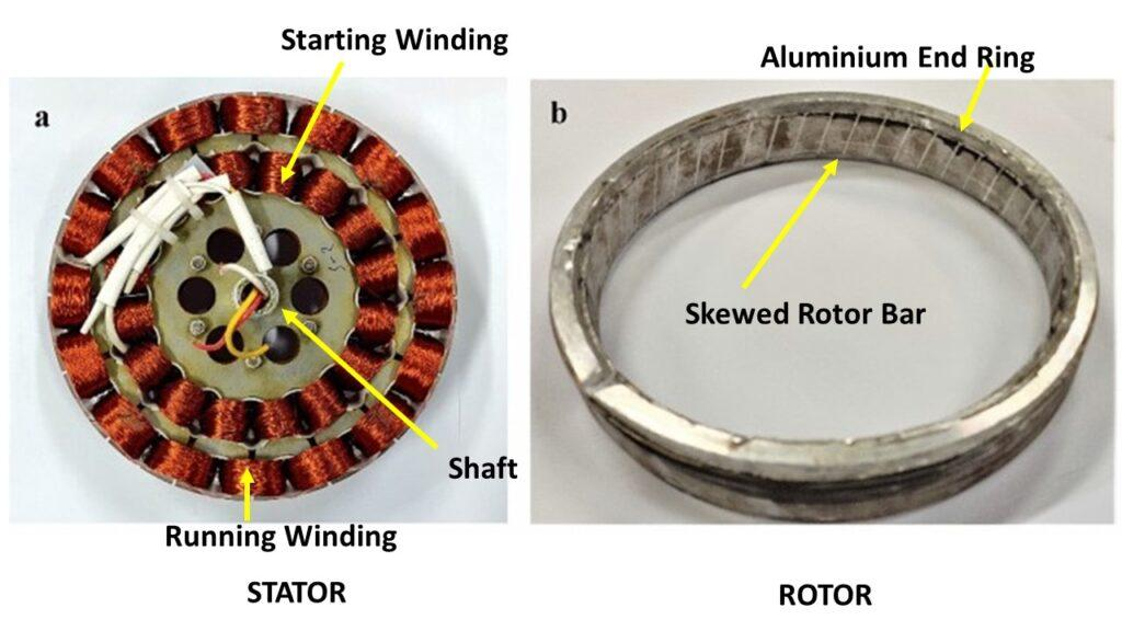
2. Why are the main and auxiliary windings different?
One interesting feature of many single-phase induction motors is that the main and auxiliary windings are not identical. The two windings have different roles in establishing the required magnetic field and can therefore be optimized differently.
The main winding is generally designed to carry the majority of the motor's continuous operating current. The auxiliary winding, on the other hand, is used to establish the required phase relationship and contribute to the rotating magnetic field. In the motor investigated in this article, the auxiliary winding occupies a different slot arrangement from the main winding.
There is a trade-off involved. Increasing the contribution of the auxiliary winding can improve the rotating-field component and potentially improve starting behaviour, but it can also increase copper losses and affect the motor's running efficiency. The objective is therefore not simply to maximize the auxiliary winding contribution: the winding arrangement must be selected to provide the required torque and operating performance while minimizing losses and cost. This is one of the areas where electromagnetic simulation becomes particularly useful.
3. Ceiling-fan efficiency and star ratings
Motor efficiency is especially important in ceiling fans because they are often operated for many hours. In India, ceiling fans are subject to energy-efficiency requirements and are assigned star ratings based on their energy performance. The star rating provides consumers with a simple way of comparing the efficiency of different products, with higher star ratings corresponding to better energy performance.
However, it is important to understand that the star rating is ultimately associated with the performance of the complete ceiling-fan product and its applicable test conditions, rather than being simply a rating of the electromagnetic motor in isolation. The achievable efficiency therefore depends on several components of the overall design, including:
- motor electromagnetic efficiency;
- bearing losses;
- mechanical losses;
- aerodynamic performance;
- operating speed;
- power factor;
- winding losses;
- core losses;
- rotor losses; and
- the operating point used for rating.
This means that improving the motor is only one part of achieving a high-rated ceiling fan.
4. Is a 5-star ceiling fan achievable with a single-phase induction motor?
A natural question is whether a conventional single-phase induction motor can achieve the efficiency required for a high energy rating. The answer is that high efficiency is possible, but it requires careful optimization of the complete motor and fan design. A single-phase induction motor has several inherent loss mechanisms.
Copper losses
The stator winding resistance produces copper losses:
Both the main and auxiliary windings contribute to copper losses. Reducing winding resistance can therefore improve efficiency, but increasing conductor size may increase the amount of copper required and affect manufacturing cost and slot utilization.
Core losses
The alternating magnetic field produces hysteresis and eddy-current losses in the stator and rotor iron. These losses depend on the magnetic flux density, frequency and electrical-steel properties. For ceiling fans, the core-loss contribution is minuscule compared with the copper losses.
Rotor losses
The induction process produces currents in the rotor, which generate rotor copper losses. Rotor losses are directly related to slip. Reducing slip generally improves the fraction of air-gap power converted into mechanical output, although the design must still satisfy torque requirements.
Mechanical losses
Bearing friction and other mechanical losses also contribute to the total input power.
Aerodynamic losses
Finally, the motor is only one part of a ceiling fan. The electrical power consumed by the fan must ultimately produce the required airflow. An efficient motor coupled with a poorly optimized blade design will not necessarily produce a highly efficient ceiling fan.
5. Where can the efficiency be improved?
There are several design variables available to the motor designer. Some of the most important are the following.
Magnetic loading and flux linkage
The stator and rotor geometry must be designed so that the motor operates at an appropriate flux density. Excessive flux density can increase core losses and potentially lead to saturation; on the other hand, reducing flux density too far may require additional turns or increase copper requirements. The optimum point is therefore a compromise.
Winding design
The main and auxiliary windings can be optimized for:
- resistance;
- leakage inductance;
- magnetizing current;
- copper utilization;
- phase displacement; and
- torque production.
The auxiliary winding is particularly interesting because its design affects both the rotating-field characteristics and the losses.
Air gap
The air gap has a significant influence on the magnetizing current and electromagnetic performance. A smaller air gap can reduce the required magnetizing current, but manufacturing tolerances and mechanical considerations limit how small the air gap can practically be.
Rotor design
Rotor bar geometry, rotor material and rotor resistance influence starting torque, slip, rotor losses, operating efficiency and torque characteristics. The rotor must therefore be designed together with the stator rather than treated independently.
6. Simulating the motor
To investigate these effects, the motor can be modelled using electromagnetic finite-element analysis. For this example, the motor geometry was created in MotorDesignSoftware. The model includes the stator geometry, rotor geometry, stator material, rotor material, main winding, auxiliary winding, electrical connection, operating voltage and frequency, and rotor motion.
The purpose of the simulation is not simply to calculate a single value of efficiency. Instead, the electromagnetic simulation lets us examine the behaviour of the motor throughout its operating cycle. The following motor was selected as the example for this analysis.
| Parameter | Value |
|---|---|
| Rated voltage | 230 V |
| Frequency | 50 Hz |
| Rated input power | 52 W |
| Rated speed | 370 rpm |
| Number of poles | 14 |
| Stator outer diameter | 125 mm |
| Stator inner diameter | 10 mm |
| Rotor diameter | 150 mm |
| Air gap | 0.3 mm |
| Capacitor | 2 µF |
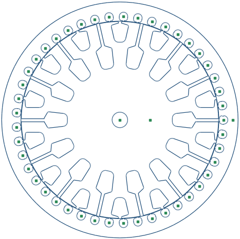
7. Magnetic field distribution
The first result worth examining is the magnetic field distribution.
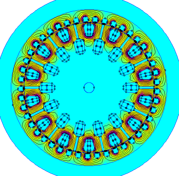
The flux-density distribution shows how the magnetic flux travels through the stator teeth, stator yoke, air gap and rotor. One of the first things to check is whether any regions of the stator or rotor are approaching excessive magnetic saturation. The simulation also provides an opportunity to identify areas where the magnetic circuit could be improved — for example, localized high flux density in a stator tooth may indicate that the tooth geometry is limiting the magnetic circuit.
8. Results
Main and auxiliary winding currents
The simulated winding currents provide another useful insight into the operation of the motor.
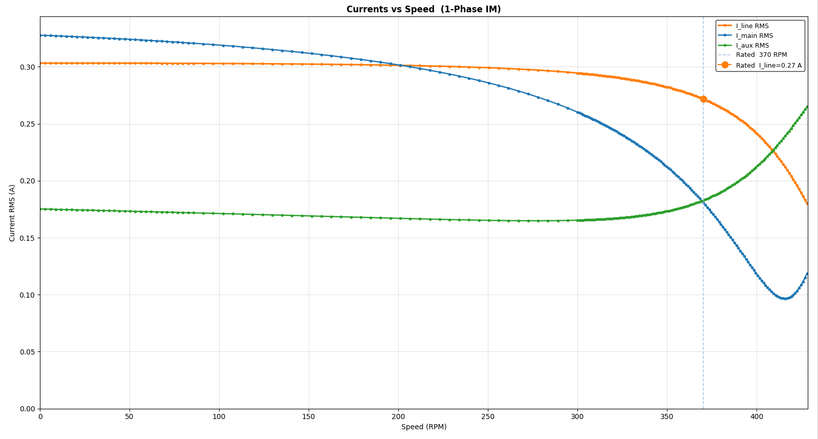
The main and auxiliary winding currents are not identical. Their magnitude and phase relationship determine the rotating-field component produced by the stator, which is particularly important when investigating why the two windings have different designs. The simulation allows the effect of changing the winding parameters to be studied without physically manufacturing a new motor for every design iteration.
8.1 Torque–speed curve
The simulated electromagnetic torque can be plotted as a function of speed.
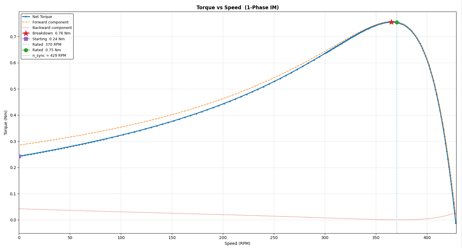
The torque–speed curve gives the torque available at any given speed which, when combined with the efficiency–speed curve, helps in optimizing the blade profile to achieve the best motor performance.
8.2 Efficiency–speed and losses
One of the most useful outputs of electromagnetic simulation is the efficiency–speed curve.
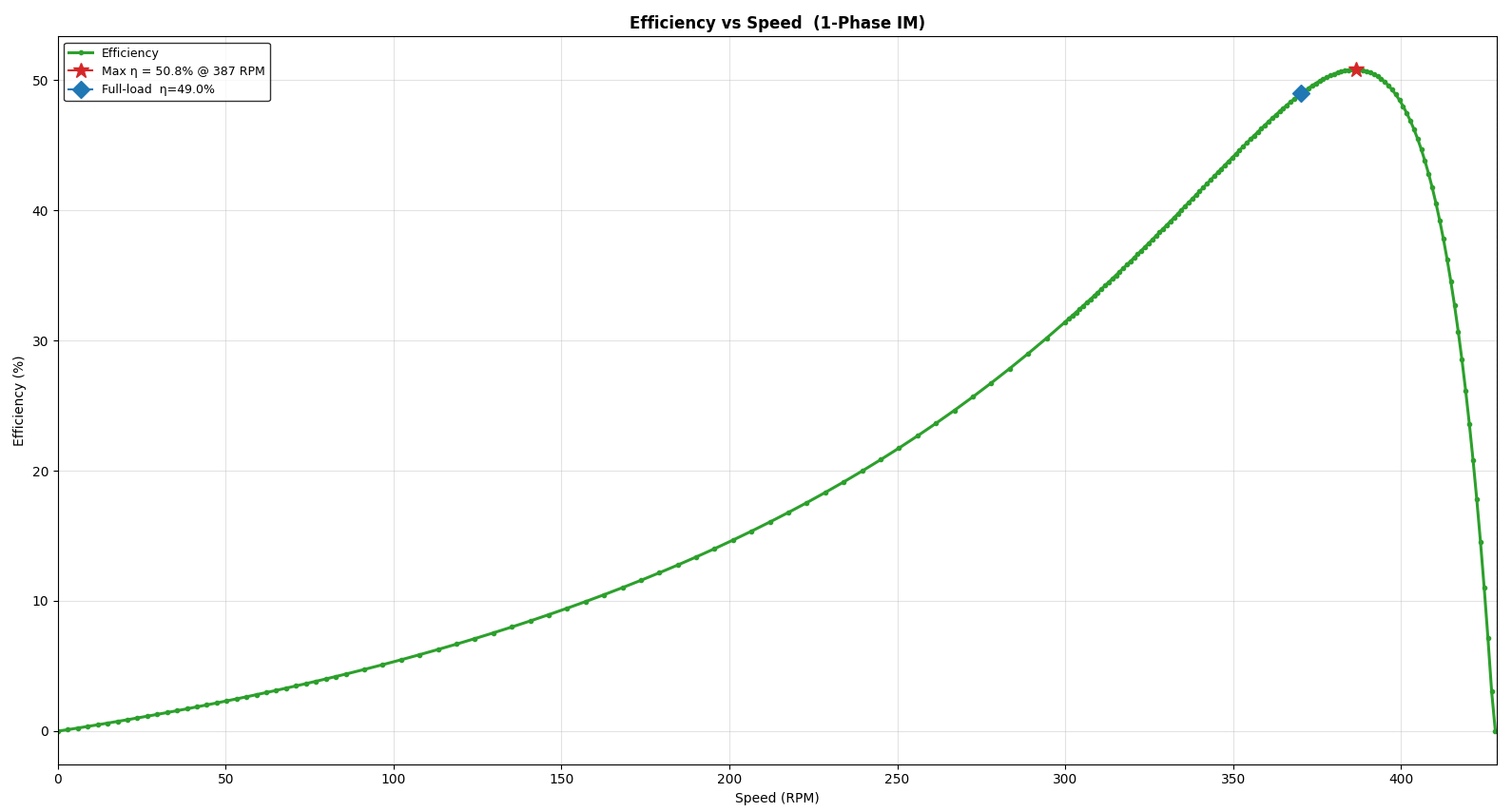
This curve, along with the torque–speed curve, gives an important data point for fan-blade optimization in order to achieve a 5-star rating. The other useful curve for optimizing the motor design is the loss-breakdown curve.
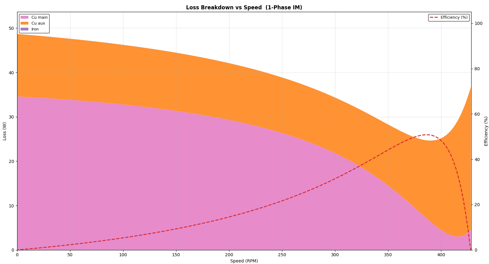
The total motor loss can be divided into several components, including the main-winding copper loss, the auxiliary-winding copper loss and the total core loss. This breakdown is particularly useful for identifying where further optimisation effort should be directed. For example, if copper loss dominates the total loss, changing the winding design may provide the largest improvement; if core loss is significant, reducing magnetic loading or selecting a different electrical steel may be more effective. This is one of the major advantages of simulation over simply measuring the input power of a prototype: simulation can provide insight into why the motor is consuming energy.
8.3 Power factor
Power factor is usually ignored by design engineers while designing motors for ceiling fans. However, power factor can significantly affect the reactive power drawn. The software provides a power-factor-versus-speed graph.
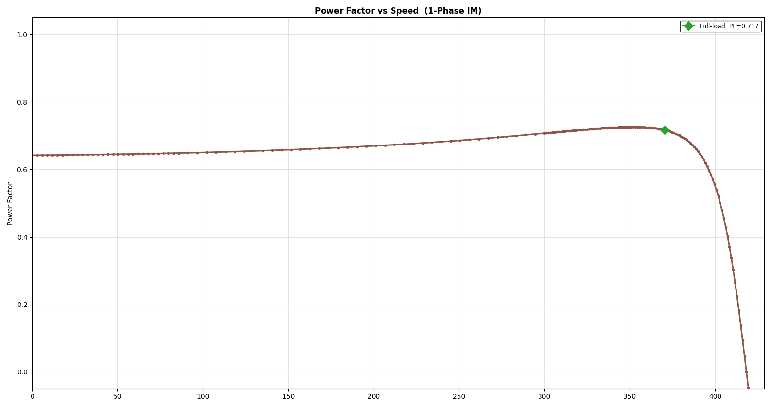
Increasing the power factor reduces the reactive power consumed by the motor, thereby increasing the total efficiency.
9. Can the motor be optimized further?
This is where electromagnetic simulation becomes particularly powerful. Once a baseline design has been established, individual design variables can be changed and the effect on performance investigated. For example, we can change:
- main winding turns;
- auxiliary winding turns;
- auxiliary winding resistance;
- capacitor value;
- air-gap length;
- rotor bar dimensions;
- stator tooth width;
- stator yoke thickness; and
- magnetic material.
Rather than changing several variables simultaneously, it is often useful to start with a controlled study where one parameter is changed at a time.
10. What does this tell us about 5-star designs?
A high star rating is not achieved through a single design change. It is the result of reducing losses across the entire system while maintaining the required airflow and operating performance. For the motor itself, the main opportunities include:
- optimizing the magnetic circuit;
- reducing stator copper losses;
- optimizing the auxiliary winding;
- reducing rotor losses;
- selecting appropriate electrical steel;
- minimizing unnecessary magnetizing current;
- reducing mechanical losses; and
- operating the motor at an efficient point.
The simulation results suggest that a well-designed single-phase induction motor can achieve substantially better efficiency than a basic low-cost design. Therefore, a 5-star ceiling fan is not inherently impossible with a single-phase induction motor. However, achieving a particular official rating requires the complete fan to satisfy the applicable regulatory test requirements — motor efficiency alone does not determine the final rating.
11. Conclusion
Single-phase induction motors remain an interesting solution for ceiling-fan applications because they offer a combination of low cost, robustness and relatively simple construction. However, achieving high efficiency requires careful electromagnetic design. The difference between the main and auxiliary windings is not simply a manufacturing convenience — their electrical and magnetic characteristics are fundamental to the operation of the motor.
Electromagnetic simulation provides a useful way of understanding these interactions. Instead of relying entirely on prototype testing, a designer can investigate the magnetic field, winding currents, torque, speed, losses and efficiency during the design stage. For the example motor investigated here, the simulation provided insight into the relationship between the winding design and the resulting motor performance, and demonstrated that there are several opportunities for further optimization.
Ultimately, achieving a high-efficiency ceiling fan requires optimization of both the motor and the aerodynamic system. A high star rating is therefore a system-level design problem rather than simply a motor-efficiency problem.
About the simulation
All electromagnetic simulations in this article were performed using MotorDesignSoftware, a motor-design and electromagnetic simulation tool developed for rapid analysis of electric machines. The software includes a template for ceiling-fan stator and rotor design, so it can be used to investigate motor geometry, winding configurations, electromagnetic performance, losses and efficiency without requiring a complete physical prototype for every design iteration.
Next steps
The baseline motor used in this article can be taken further by performing a systematic optimization study. Some interesting questions to investigate are:
- How much can efficiency be improved by changing the auxiliary winding?
- What is the optimum capacitor value?
- How does the air gap affect efficiency?
- What happens when the rotor resistance is changed?
- Which losses dominate the motor?
- How much improvement is possible before manufacturing constraints become the limiting factor?
These questions can be investigated using the same electromagnetic model and provide a useful starting point for the optimization of high-efficiency ceiling-fan motors.
← Back to all articles