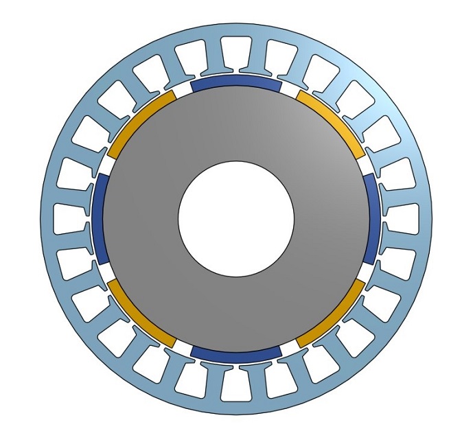
Magnetic Equivalent Circuit (MEC) analysis for Surface Permanent Magnet motors
Motor Configuration
Solver
⚡ MEC — Magnetic Equivalent CircuitClient-side analytical solver · No FEA license required
Inner Rotor SPM
🧱 Material Selection
▼
🔵 Stator Geometry
▼
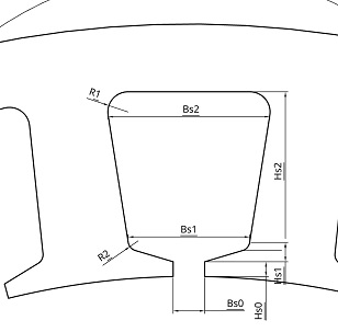
Slot bridge height
Slot wedge height
Main slot body height
Slot opening width at air-gap
Tooth width ≈ slot_pitch − Bs2
🔴 Rotor Geometry (SPM)
▼
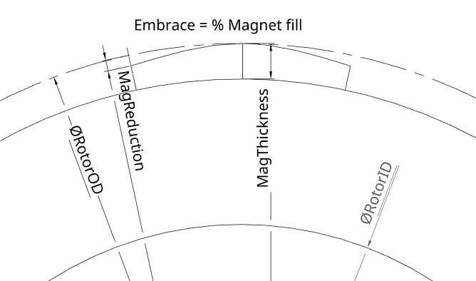
Radial magnet thickness
Magnet arc / pole pitch ratio
Magnet-to-rotor-bore gap (if any)
📐 Stack & Skew
▼
Inner Rotor — Stator & SPM
Winding Configuration
Winding Layout Table
Coil #
In Slot
Out Slot
Phase
Turns
Winding Calculations
—
Slot Fill Factor
—
Slot Area (mm²)
—
DC Resistance per Phase (Ω)
—
Resistance @ Temp (Ω)
—
Mean Turn Length (mm)
—
Series Turns / Phase
Operating Point
Loss Configuration
Simulation Modules
MEC Solver
⚡ MEC
Analytical d-q model with Carter's coefficient air-gap correction, Bertotti core loss model, and field-weakening for the torque–speed envelope.
0%
Initializing…
⚠️
MEC Accuracy Notice
Results are generated by a Magnetic Equivalent Circuit (MEC) analytical model. While MEC provides fast first-order estimates, it does not model saturation, slot-leakage harmonics, or complex 2D/3D field effects. Results may deviate from FEA/experimental values by 5–25%. Always validate critical designs with FEA (e.g., FEMM) before manufacturing.
Simulation Results
⚡ MEC
No results yet. Run a simulation from the Simulation tab.
Drive
DC Bus Voltage—
Available Phase Voltage—
id (d-axis current)—
iq (q-axis current)—
Max Speed—
kt—
ke—
Material & Weights
Stator Material—
Rotor Material—
Magnet Material—
Stator Weight—
Rotor Weight—
Winding Weight—
Magnet Weight—
Total Weight—
Rotor Inertia—
Torque
Average Torque—
Max Torque—
Min Torque—
Torque Ripple—
Power & Losses
Speed—
Output Power—
Copper Loss—
Core Loss—
Magnet Loss—
F&W Loss—
Total Losses—
Input Power—
Efficiency—
Back-EMF (No Load)
RMS Phase Back-EMF—
Peak Phase Back-EMF—
Peak-to-Peak Back-EMF—
Back-EMF THD—
Air-Gap & Flux Density (No Load)
Air-Gap Flux Density (avg)—
Air-Gap Flux Density (peak)—
Stator Tooth B—
Stator Yoke B—
Rotor Yoke B—
Winding
DC Resistance (per phase, 20°C)—
Resistance @ Temperature—
k_ac Ratio—
Fill Factor—
Ld (d-axis inductance)—
Lq (q-axis inductance)—
ψ_pm (flux linkage)—
Winding Factor (kw)—
⚠️
MEC Accuracy Notice
All graphs are generated by the MEC analytical model. Waveforms are sinusoidal approximations — harmonic content from slot effects, saturation, and fringing is not captured. Use FEA for waveform fidelity validation.
No simulation results yet. Run a simulation to generate graphs.
Phase Back-EMF Waveform (V)
Cogging Torque Waveform (Nm)
Torque Ripple Waveform (Nm)
Phase Current Waveform (A)
Torque–Speed Curve
Power vs Speed (W)
Efficiency Map — Torque vs Speed (Filled Contour)
PMSM Motor Analysis: MEC Solver, Back-EMF, Cogging & Efficiency
This free motor calculator runs a fast analytical Magnetic Equivalent Circuit (MEC) simulation of a surface-permanent-magnet (SPM) synchronous motor right in your browser. From a handful of geometry, magnet and winding inputs it estimates the back-EMF, cogging torque, average torque and ripple, the efficiency map and the torque–speed envelope — the same quantities you would normally wait minutes for from a finite-element solver, delivered in a fraction of a second so you can sweep designs interactively.
What is a Magnetic Equivalent Circuit?
A magnetic equivalent circuit models the motor's magnetic field as a network of reluctances and MMF sources — the magnetic analogue of a resistor network. Air gaps, teeth, yokes and magnets each become a reluctance, and solving the network yields the air-gap flux density. Because it is analytical rather than mesh-based, an MEC solver is orders of magnitude faster than FEA while capturing the dominant physics, which makes it ideal for early sizing, parameter sweeps and optimisation before committing to a full finite-element run.
Back-EMF and the torque constant
When the rotor spins, the moving magnet flux induces a back-electromotive force (back-EMF) in the stator windings. Its amplitude scales with speed through the back-EMF constant ke, and its shape — how sinusoidal it is — directly affects torque ripple and how well the motor suits sinusoidal (field-oriented) versus trapezoidal (six-step) control. In a PM synchronous machine the torque constant and back-EMF constant are two sides of the same magnetic coin, so a clean, high back-EMF is the foundation of an efficient, smooth motor.
Cogging torque and torque ripple
Cogging torque is the position-dependent torque present even with no current, caused by the magnets' tendency to align with the stator teeth. Torque ripple is the variation in torque under load. Both cause vibration and acoustic noise and are strongly influenced by the slot/pole combination, magnet geometry, pole embrace and any skew. The calculator estimates the cogging period and amplitude alongside the average torque, so you can judge smoothness up front.
The d–q model, saliency and MTPA
Field-oriented control transforms the three-phase machine into an equivalent two-axis (d–q) model with a direct-axis inductance Ld and a quadrature-axis inductance Lq. Torque comes from two terms:
T = (3/2) · p · [ ψm Iq + (Ld − Lq) Id Iq ]
The first term is the magnet torque; the second is reluctance torque from any saliency (Ld ≠ Lq). Maximum-Torque-Per-Amp (MTPA) control picks the current angle that extracts the most torque for a given current, minimising copper loss. This tool can evaluate the operating point using MTPA, a zero d-axis current, or a custom excitation.
Losses and the efficiency map
Efficiency is set by the balance of output power against losses. The calculator accounts for the major mechanisms:
Copper (I²R) loss in the windings, corrected for operating temperature.
Core loss in the laminated steel, using a Bertotti-style hysteresis-plus-eddy model that scales with flux density and frequency.
Magnet eddy-current loss, significant at high speed and reduced by segmenting the magnets.
Windage and friction, entered as a mechanical loss term.
Mapping efficiency across the full torque–speed plane produces the familiar efficiency map, which reveals where the motor is most efficient and guides gearing and duty-cycle decisions.
Torque–speed curve and field weakening
Every PM motor has a base speed, reached when the back-EMF meets the available inverter voltage. Below it the machine delivers constant torque; above it, field weakening (negative d-axis current) trades torque for extended speed at roughly constant power. The calculator plots the resulting torque–speed and power–speed envelopes for your DC-bus voltage and current limits.
How to use this motor calculator
Enter the stator and rotor geometry, magnet grade and dimensions, and the winding and steel properties.
Set the operating current, DC-bus voltage and speed, and choose the drive method (MTPA, Id = 0, or custom).
Enable the loss components you care about (copper, core, magnet eddy, windage).
Read the back-EMF waveform, cogging and torque curves, d–q parameters, efficiency map and torque–speed envelope.
Frequently asked questions
How accurate is an analytical MEC compared with FEA?
For surface-PM machines an MEC captures the dominant air-gap and back-EMF behaviour well and is excellent for ranking designs and sweeping parameters. Absolute figures — especially deep saturation, complex rotor geometries and fine cogging detail — are best confirmed afterwards with full FEA, which the desktop suite automates.
Why does the back-EMF shape matter?
A sinusoidal back-EMF pairs naturally with field-oriented control for smooth, low-ripple torque; a trapezoidal shape suits six-step drive. Mismatching the waveform and the control strategy increases torque ripple and losses.
What is the reluctance torque term?
When Ld and Lq differ (a salient rotor), the machine produces extra torque from the rotor's magnetic anisotropy, on top of the magnet torque. Interior-PM and synchronous-reluctance machines exploit this heavily.
When you are ready to move from analytical estimates to a validated design, the full MotorDesignSoftware desktop suite builds the FEMM geometry and runs complete finite-element back-EMF, cogging, torque-ripple, loss and NVH analyses automatically.