Flux LUT — Pretty Graphs and Their Significance
Why do we need a Flux LUT for motor control?
When designing a motor, we often calculate Ld and Lq and use them as fixed motor parameters. This works reasonably well when the motor is operating in a relatively linear region.
But as discussed in the previous blog, motor inductance can change significantly with current once the magnetic circuit starts to saturate. So instead of a single Ld and Lq, what if we could describe them across the entire operating range? This is where a Flux LUT becomes useful.
1. What is a Flux LUT?
A Flux LUT, or Flux Look-Up Table, describes the motor's magnetic behavior over a range of Id and Iq currents. Instead of treating each inductance as a single fixed value:
we describe them as a function of the operating point:
In other words, the inductances are no longer treated as constant — they change depending on the motor's operating point.
2. Why do Ld and Lq change?
The main reason is magnetic saturation. At low current the magnetic circuit is relatively linear (unless you already saturate the motor with rotor magnets). As current increases, parts of the stator and rotor begin to saturate.
The amount of saturation depends on both Id and Iq, so the inductance cannot necessarily be described using only one current value. This means the d-axis and q-axis inductances change depending on the operating point (remember the two graphs from the last blog). It is also why the apparent and incremental inductances discussed there can produce different results at high current.
3. How is the Flux LUT generated?
The basic idea is relatively simple: a number of electromagnetic simulations are performed at different combinations of Id and Iq.
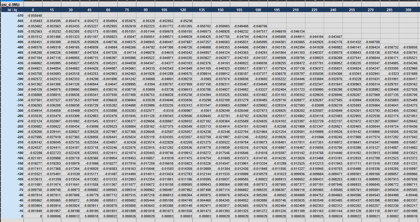
At each operating point the flux linkage is calculated. From these results the relationship between current and flux linkage can be obtained, and from that we compute Ld and Lq as a function of Id and Iq (using either of the two methods from the last blog). MotorDesignSoftware can generate these maps and provide the resulting data to the user.
4. Why is this useful for motor control?
A motor controller needs to know how the motor will respond to a particular current command. For a simplified motor model, we might use constant values of Ld and Lq, for example:
If Ld and Lq are assumed constant, these equations are only an approximation of the actual motor. For a motor with significant saturation, the real inductance can be quite different from the assumed value. Using a Flux LUT lets the controller or motor model use the inductance corresponding to the current operating point.
5. Apparent vs incremental inductance
The inductance in the LUT can be calculated by two methods — apparent inductance and incremental inductance.
6. What does the LUT look like?
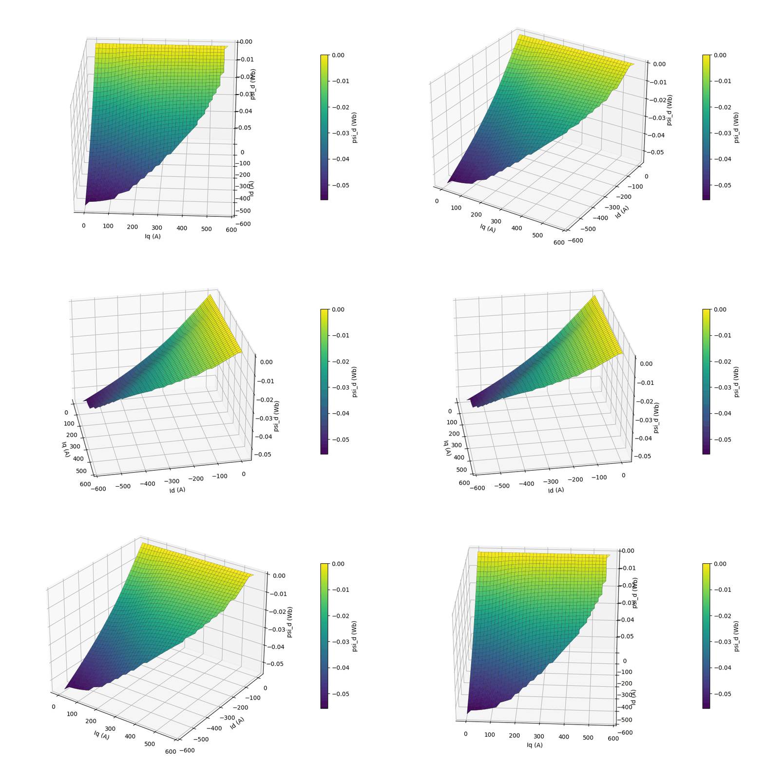
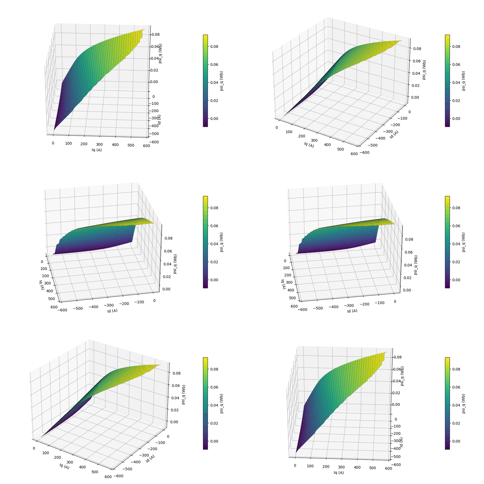
Flux linkage vs Id, Iq
Inductance vs Id, Iq
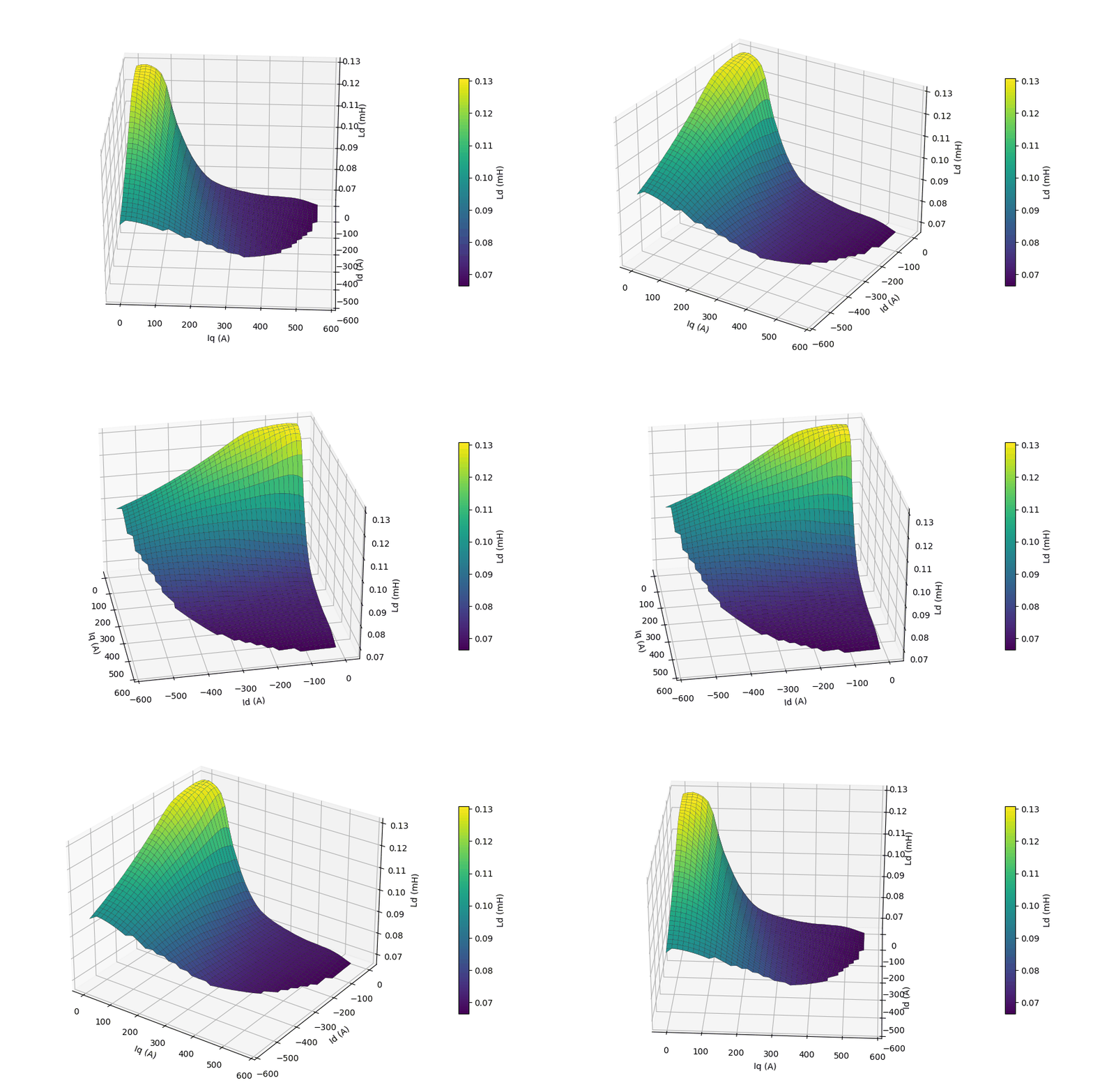
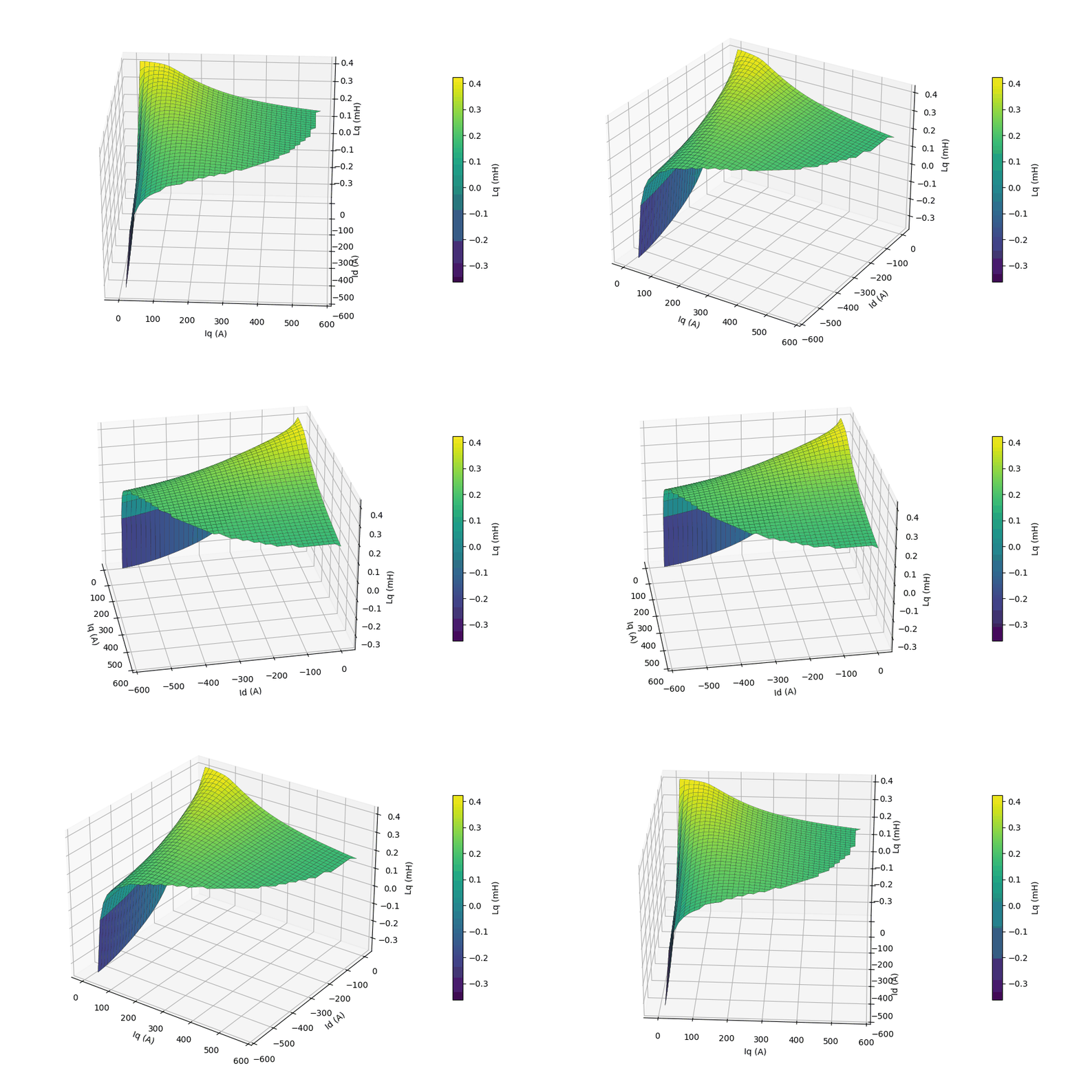
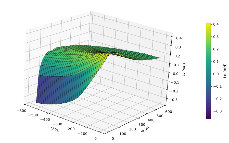
The shape of these surfaces gives a visual representation of the motor's saturation behavior. In the less-saturated region the inductance changes relatively slowly; as the motor moves into stronger saturation, the surfaces change more rapidly. This is something you cannot see when the motor is represented by a single Ld and Lq value.
7. Is it needed in real applications?
A Flux LUT becomes particularly useful when the motor operates over a wide current range. Some examples:
- high-torque operation
- Maximum Torque Per Ampere (MTPA)
- flux weakening
- high-speed operation
- current-loop modelling
- detailed motor-drive simulation
For a motor that stays mostly unsaturated, a constant-inductance model may be perfectly adequate. For a highly saturated motor, the difference between a constant-parameter model and a saturation-aware model can become significant.
8. From motor design to motor control
This is one of the interesting connections between motor design and motor control. The electromagnetic designer calculates the motor's magnetic behavior using FEA; the control engineer then uses that information to build a more accurate motor model. The process can be thought of as:
Instead of assuming the motor behaves linearly, the control model can now use the actual magnetic characteristics obtained from the motor simulation.
9. Conclusion
A single Ld and Lq value can be useful for a basic motor model, but it does not describe the complete behavior of a saturated motor. A Flux LUT represents the motor's magnetic behavior across a range of Id and Iq, making the model more representative of the actual machine — particularly when the motor operates close to saturation or over a wide speed and torque range.
For motor designers, it also provides a useful way of passing information from electromagnetic design into the motor-control stage (and awesome graphs as well). MotorDesignSoftware provides these Ld(Id,Iq) and Lq(Id,Iq) maps along with the dataset, so users can investigate the motor's behavior beyond a single operating point.
About the simulation
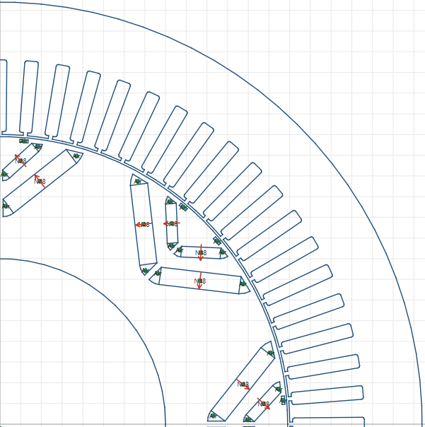
The data in this blog is from a Chevy Bolt motor, simulated in MotorDesignSoftware using FEMM.
← Back to all articles